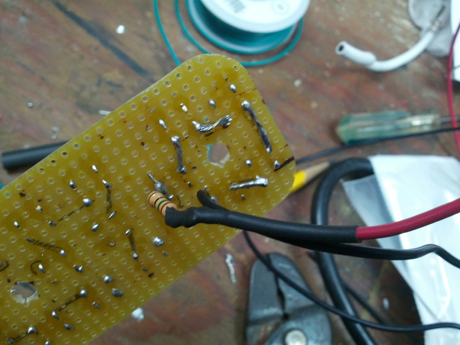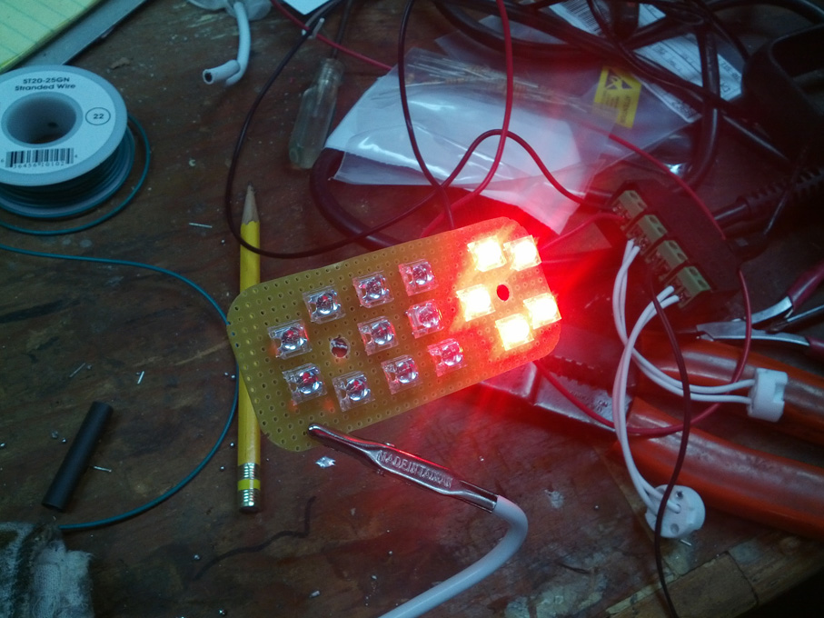
So I got a bit more done last night with the LED lights, but got a bit frustrated with the slow progress. Having to manually build bridges between each LED either by solder or wire (both a royal pain at that size) was starting to get rather tedious. At one point I exclaimed aloud “why didn’t I just do this with a printed PCB setup?”… and then I stopped and thought… “wait… why *don’t I* just do this with a printed PCB setup?”. I got a bit farther along, and after blinding myself with a test of the brake light running lights, decided to call it a night and do some reading.
A bit of digging around turned up more than a few sources of light-sensitive copper clad boards (even Fry’s… which was a bit surprising). The only downside I’ve discovered is that I haven’t come across any with the grid holes already drilled. While this isn’t in any way a deal breaker (CNC router, hello~!), it does mean a slight bit more setup time. I stopped to ask my electrical engineer coworker if he’d seen the kits for doing these kinds of things before, and that proved to be a very smart move.
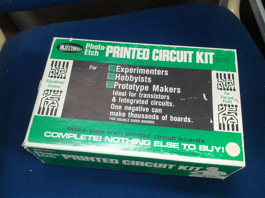
He had me follow him to the tools / chemicals cabinet on the company’s assembly floor, and dug out a whole “DIY Copper Clad PCB” kit that he’d said had been sitting around for a long while and no one had touched it. I grabbed it and made off with it and some laserjet transparency film we haven’t used in years, and now I’m going to start designing the circuits for the MogRod LED Lights 2.0! This does mean I’m going to have to reorder the LED’s, as I would rather do that than waste more time trying to de-solder all of them. It’s such a small cost in the scheme of things that it’s worth doing so, though.